Experience can be a brutal teacher, so we are going to try to pass on lessons we’ve learned to help you save money and limit these budget busters, hopefully preventing you from learning the hard way.
THE ISSUE:
Of all the different costs associated with a project development, the most volatile and by far the hardest one to estimate are the costs of site work. Out of all components of site work costs, encountering unexpected rock can utterly destroy a project budget. One foot of rock covering an acre can cost $ 40,000 to $ 80,000 to remove, one foot over 10 acres can cost $ 400,000 to $ 800,000 to remove, and two feet of rock covering 10 acres and you are easily spending millions of dollars above projected costs. To get a better idea of what is under the surface on the property you are working with, a due diligence report or preliminary site analysis should involve subsurface investigations. Its money well spent.
STANDARD SOLUTION:
The most common method used for subsurface investigations are borings. A drill rig is used to take soil borings at a specific location on the site. The borings reveal the composition and characteristics of the soil, elevation of the water table, and presence of rock. The problem with borings is that they only can tell you what is located directly in the boring hole itself. What is located 10 feet, 20 feet, or further horizontally from the initial boring hole is unknown. We can assume it is be made up of the same soil and conditions, but there is no guarantee. This is why all soil investigation reports have very specific disclaimers to this effect telling the client that conditions might greatly vary between borings.
So in order to gain a better picture of what is most likely under the ground, you need to drill additional borings. The more borings you do, the clearer the picture you have of what is under the surface. That said, borings are expensive and no one wants to, or can afford to turn their site into a piece of swiss cheese. Yet, one of the biggest mistakes developers can make is to significantly limit the number of borings to save money. This approach is quite a gamble and will increase the risk of unknown rock exposure in an effort to save money.
BREWER ENGINEERING’S APPROACH:
One possible alternative we would recommend with your subsurface investigation is to consider using Seismic Refraction. Using Seismic Refraction in combination with borings is a great economical option to increase the understanding of what is under ground and reduce the number of borings required.
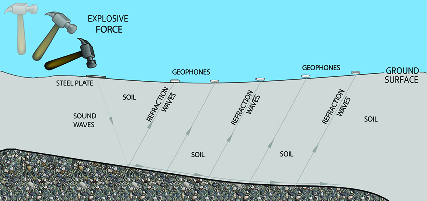
Seismic Refraction is a method that uses a set of geophones arrayed in a line to record seismic waves generated by an explosion (like a hammer strike on a steel plate – See Figure 1). The geophones record the reflective and refractive waves generated by the hammer strike. From that information the velocity of the waves travelling through the soil can be measured and the density of the materials can be calculated.

Figure 1
The varying densities can be placed on a graph revealing the denser materials like rock from the less dense materials like soil (See Figure 2).

Figure 2
There are however, a few limitations with Seismic Refraction. Seismic Refraction can’t tell you exactly what the material is and its characteristics. For example, rock and water appear to be the same substance when using Seismic Refraction. Pairing this method with a limited number of borings can most easily combat this issue, and provide the best of both methods.

Figure 3
Seismic Refraction lines can be set up about 230 feet long. Orienting the refraction lines to intersect with boring locations in a grid approach allows the boring data to be used to calibrate the seismic refraction data. Seismic data combined with the actual boring can provide a much clearer understanding of the subgrade. See Figure 3.
BREWER ENGINEERING CASE STUDY
On a recent project, Brewer Engineering recommended this approach for a 30 acre development. The site was previously cleared, so access to the site was excellent. A series of seismic refraction lines (L lines from the figure 3) in combination with a few boring locations (B-# from the figure 3) were oriented in a grid pattern. Intersection between borings and the traverse lines were maximized, so that calibration of the seismic information could be compared to actual boring results. A total of 10 boring locations ( 20 – 40 ft) and 31 seismic refraction traverse lines each 230 ft long were used to cover a 25 acre area of the site. The total cost for this including a Subsurface Investigation Report was under $10,000.
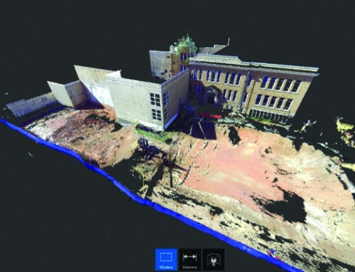
Brewer Engineering took the results from this testing and interpolated between traverse lines to create a 3D model of the rock surface. This information was used to help determine the most economical elevation of the proposed buildings. Using the 3D rock surface model, the design team was able to determine the optimum elevations. In this instance, rock removal was required to create the best possible relationship of the building to the street level. This information was critical to the design of plumbing and utilities under the building, allowing engineers to design around rock exposed area. In addition, we were able to estimate the total quantity of mass rock and trench rock we would have to move. After all rock removal was accomplished on the project, the 3D model estimate of rock removal was within 3% of the actual amount of rock encountered. Not bad for an investment just under $ 10,000.
We hope that with your next subsurface investigation, you consider using seismic refraction; it could help save you hundreds of thousands of dollars of unexpected rock removal.
HOW CAN BREWER ENGINEERING HELP?
If you have further questions on seismic refraction, or are interested in how Brewer Engineering can help you on your next subsurface investigation, please don’t hesitate to contact us for further information.
